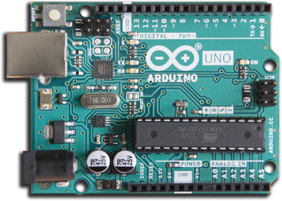
ESP8266 ARDUINO CON WIFI

CARACTERÍSTICAS DEL ESP8266
Sketch
/*
  DigitalReadSerial

  Reads a digital input on pin 2, prints the result to the Serial Monitor

  This example code is in the public domain.

  http://www.arduino.cc/en/Tutorial/DigitalReadSerial
*/

// digital pin 2 has a pushbutton attached to it. Give it a name:
int pushButton = 2;

// the setup routine runs once when you press reset:
void setup() {
  // initialize serial communication at 9600 bits per second:
  Serial.begin(9600);
  // make the pushbutton's pin an input:
  pinMode(pushButton, INPUT);
}

// the loop routine runs over and over again forever:
void loop() {
  // read the input pin:
  int buttonState = digitalRead(pushButton);
  // print out the state of the button:
  Serial.println(buttonState);
  delay(1);        // delay in between reads for stability
}
2 - En el
void setup(){
  pinMode(LedPin,OUTPUT);    // Salida Digital
  pinMode(BotonPin,INPUT);   // Entrada Digital
}
En el
3 - digitalRead()
valor = digitalRead(BotonPin); // Leemos el estado del boton HIHG/LOW
Lee el valor/estado del pin digital. Su valor será HIGH o LOW.
digitalRead(pin)
4 - digitalWrite()
Escribe un valor HIGH o un LOW en un pin digital.
digitalWrite(LedPin,HIGH);} // Encendemos el LED
digitalWrite(pin, value)
void loop(){
valor = digitalRead(BotonPin); // Leemos el estado del boton HIHG/LOW
if  (valor == HIGH){                // Condición si valor es igual a HIGH
  digitalWrite(LedPin,HIGH);}       // Encendemos el LED
  else { digitalWrite(LedPin,LOW);} // Sino, apagamos el LED
}
El en loop() encontramos la primera una estructura de control
5 - if
La estructura de control if verifica si se cumple una condición y ejecuta una declaración o el conjunto de declaraciónes.
if (condición) {//declaración(s)}
(condición): una expresión booleana (es decir, puede ser verdadero o falso).
Otra estructura de control:
6 - else
Con la estructura de control else se puede proceder con otra prueba
else if (condición 2) {//declaración(s)}
Igual que
Podemos probar con motores, buzzers y otros actuadores que admitan valores digitales.