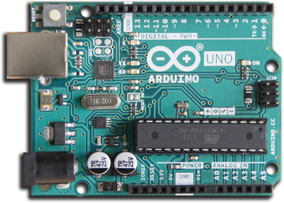
ESP8266 ARDUINO CON WIFI

CARACTERÍSTICAS DEL ESP8266
Sketch
/*
  Analog input, analog output, serial output

  Reads an analog input pin, maps the result to a range from 0 to 255 and uses
  the result to set the pulse width modulation (PWM) of an output pin.
  Also prints the results to the Serial Monitor.

  The circuit:
  - potentiometer connected to analog pin 0.
    Center pin of the potentiometer goes to the analog pin.
    side pins of the potentiometer go to +5V and ground
  - LED connected from digital pin 9 to ground

  created 29 Dec. 2008
  modified 9 Apr 2012
  by Tom Igoe

  This example code is in the public domain.

  http://www.arduino.cc/en/Tutorial/AnalogInOutSerial
*/

// These constants won't change. They're used to give names to the pins used:
const int analogInPin = A0;  // Analog input pin that the potentiometer is attached to
const int analogOutPin = 9; // Analog output pin that the LED is attached to

int sensorValue = 0;        // value read from the pot
int outputValue = 0;        // value output to the PWM (analog out)

void setup() {
  // initialize serial communications at 9600 bps:
  Serial.begin(9600);
}

void loop() {
  // read the analog in value:
  sensorValue = analogRead(analogInPin);
  // map it to the range of the analog out:
  outputValue = map(sensorValue, 0, 1023, 0, 255);
  // change the analog out value:
  analogWrite(analogOutPin, outputValue);

  // print the results to the Serial Monitor:
  Serial.print("sensor = ");
  Serial.print(sensorValue);
  Serial.print("\t output = ");
  Serial.println(outputValue);

  // wait 2 milliseconds before the next loop for the analog-to-digital
  // converter to settle after the last reading:
  delay(2);
}
1 - Asignamos el
const int PotPin = 0; // Asigna el potenciómetro al pin A0 (analoógico) de 0 a 1023.
2- El
3 - Declaramos la
4 - Especificamos que el pin del potenciómetro es de
5 - Iniciamos la comunicación
const int LedPin = 11; // Asigna el Led al pin ~11(PWM) byte de 0 a 255.
Vayamos a la página oficial de arduino y veamos lo que nos dice sobre:
Variables
#define nombreConstante valor
#define LedPin 11
// Asigna al Led el Pin 11
En este ejemplo encontramos const que modifica la variable como solo lectura que suele ser la mas habitual:
const int NombreActuador/Sensor = PinNumero;
const int LedPin = 11;
// Asigna al Led el Pin 11
Por último la otra forma de encontrarla es con una variable numérica:
int NombreActuador/Sensor = PinNumero;
int LedPin = 11;
// Asigna al Led el Pin 11
6 - analogRead()
valor = analogRead(PotPin); // Guardamos el valor del pin A0 en la variable.
Lee el valor del pin analógico especificado. Las placas Arduino contienen un convertidor analógico a digital multicanal de 10 bits. Esto significa que asignará los voltajes de entrada entre 0 y el voltaje especificado (5V o 3.3V) en valores enteros entre 0 y 1023. En un Arduino UNO, por ejemplo, esto produce una resolución entre lecturas de: 5 voltios / 1024 unidades o , 0.0049 voltios (4.9 mV) por unidad.
7 - analogWrite()
Escribe un valor analógico-PWM de 0 a 255 (byte) en un pin. Se puede usar para encender un LED con diferente intensidad o girar un motor a diferentes velocidades. Después de una llamada a analogWrite(), el pin generará una onda rectangular estable del ciclo de trabajo especificado hasta la próxima llamada a analogWrite().
analogWrite(LedPin, valor/4); // Escribimos en el potenciómetro salida PWM.
Podemos probar con motores, buzzers y otros actuadores que admitan valores analógicos.